
Chassis Instructions – Hammer Head JDS2020
JDS 2020 – Hammerhead Nobar
(photos below)
The Hammerhead is JDS first nobar chassis. This chassis is perfect for bracket and Stock and Super Stock classes and features the same ultra-strong motor box JDS has become famous for.
JDS uses premium .035 Spring Steel and the latest laser cutting technology. Unlike the stainless steel used by others, JDS spring steel chassis will last for many years and provide consistent performance pass after pass. Our chassis are famous not just for performance – but also for how our chassis go together without modification unlike many of our competitors.
SAFETY PRECAUTIONS
- Always wear safety equipment to protect your face and eyes while assembling the chassis.
- Work in a well-lit location with good ventilation.
- Read and follow all manufacturers’ safety precautions when using tools and soldering equipment.
- Take your time and work carefully. The finished product is well worth the time you put into it.
ASSEMBLY INSTRUCTIONS
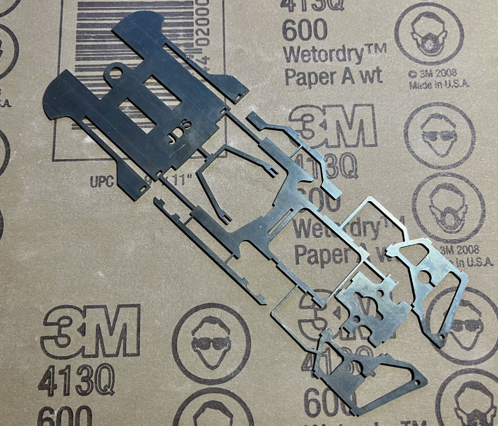
Using 600 grit wet/dry sandpaper, sand the areas on the chassis and uprights parts where you plan to solder. You only need to sand enough to remove the top coating of the bluing on the metal. Photo 1
NOTE: You may find it easier to sand the pieces prior to cutting them apart. Simply put a full piece of 600 grit wet dry paper on your bench and rub the chassis on it. Some touch up may be need once cut apart, for this we suggest using a wire wheel in your rotary tool.
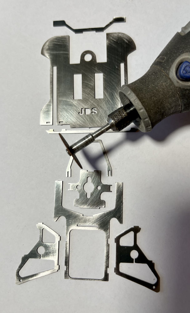
Using your rotary tool and a cutoff wheel carefully cut the pieces apart. Be sure to cut the pieces off flush and remove any burr that may be left behind. Photo 2
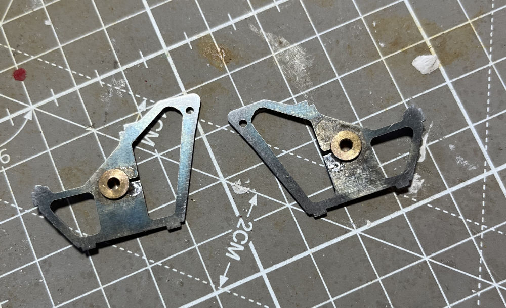
Begin by spot soldering an oilite bushing to each of the axle uprights. Photo 3
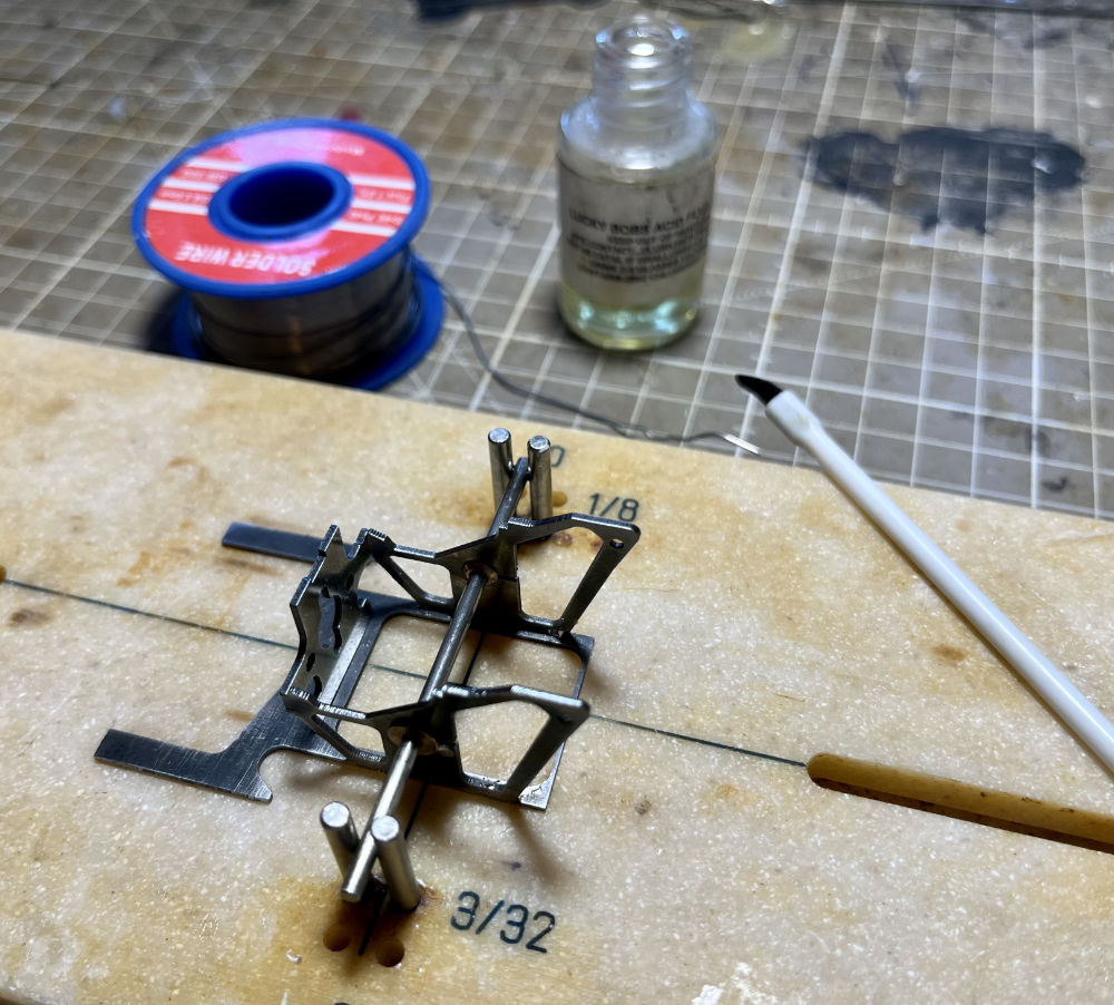
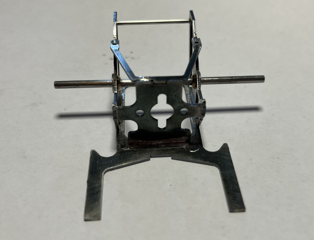
Using your chassis jig place the rear section between the two sets of axle locators on your jig. Then push your axle through the axle uprights and your chassis jig axle locators. Next place the motor plate into the slot in the base then tilt it up and into the tabs on the uprights. Photo 4
NOTE: The hole for the motor bushing is offset. When looking from the front be sure the hole is offset to the right. Photo 5
Tack solder the uprights to the base at the inside of the rear of the base. Then solder the two upright tabs to the motor plate. Next set the wishbone in place with the two notches over the tabs on the up rights and the tab at the front of the wishbone in the notch in the top of the motor plate. Tack solder the wishbone to the two uprights. NOTE: Your jig axle should be able to slide freely through the oilites at this point.
You may now solder the motor plate to the base and finish soldering the uprights to the base.
Remove the rear section from the jig and flip it over so you may solder the front of the wishbone to the top of the motor plate from the bottom side.
Last take a piece of .050 stainless or music wire and slide it into the two holes at the top rear of the up rights and solder. Use your Dremel to cut this off flush on both sides with the upright.
You may now finish soldering in your oilites.
NOTE: Be sure to put a drop of oil on the axle and slide back and forth to ensure you do not solder the oilites to the axle! If you are using bearings, be sure to put a drop of oil on each side of the bearing to keep the acid flux out of the bearing. Oilites and or bearings also may be installed using two-part epoxy or Loctite.
Take the finished rear section of the chassis and wash thoroughly with warm water and dish soap using an old toothbrush to scrub all the solder joints.
NOTE: If using a large pinion, when the rear section is complete, you may use your cutoff tool to cut a slot in the motor plate the width of the armature shaft (2mm). This will allow you to easily install your motor with the pinion in place. We do not use a large pinion holed motor plate to accommodate big pinions. Motor plates with large pinion holes can make motor alignment and installation difficult. It is very important that the center of your armature is perfectly aligned and 90 degrees to the rear axle. Our standard sized motor bushing hole makes motor installation a snap and ensures proper alignment.
Now let’s move on to the front section…
NOTE: There are some variations of assembly both the tube length, and location as well as music wire size for tuning purposes. Here we’ve soldered the tubes at the front of the slot and used .062 music wire. Be sure to lightly sand all the brass and music wire with some 1000-1500 wet dry sandpaper before soldering.
Cut two pieces of 1/8” brass tube ½”- ¾” long and solder into the outer slots of the nose piece (JDS should face down). In this case we used ¾” tubes and soldered all the way to the front…
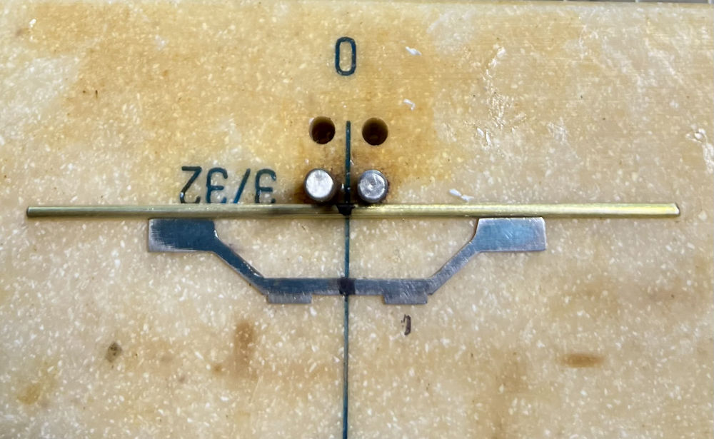
Next use a piece of 1/16” brass tube to make your front axle. Measure your body width at the front wheel opening and cut accordingly. Now install your front axle to the axle mount. Photo 6
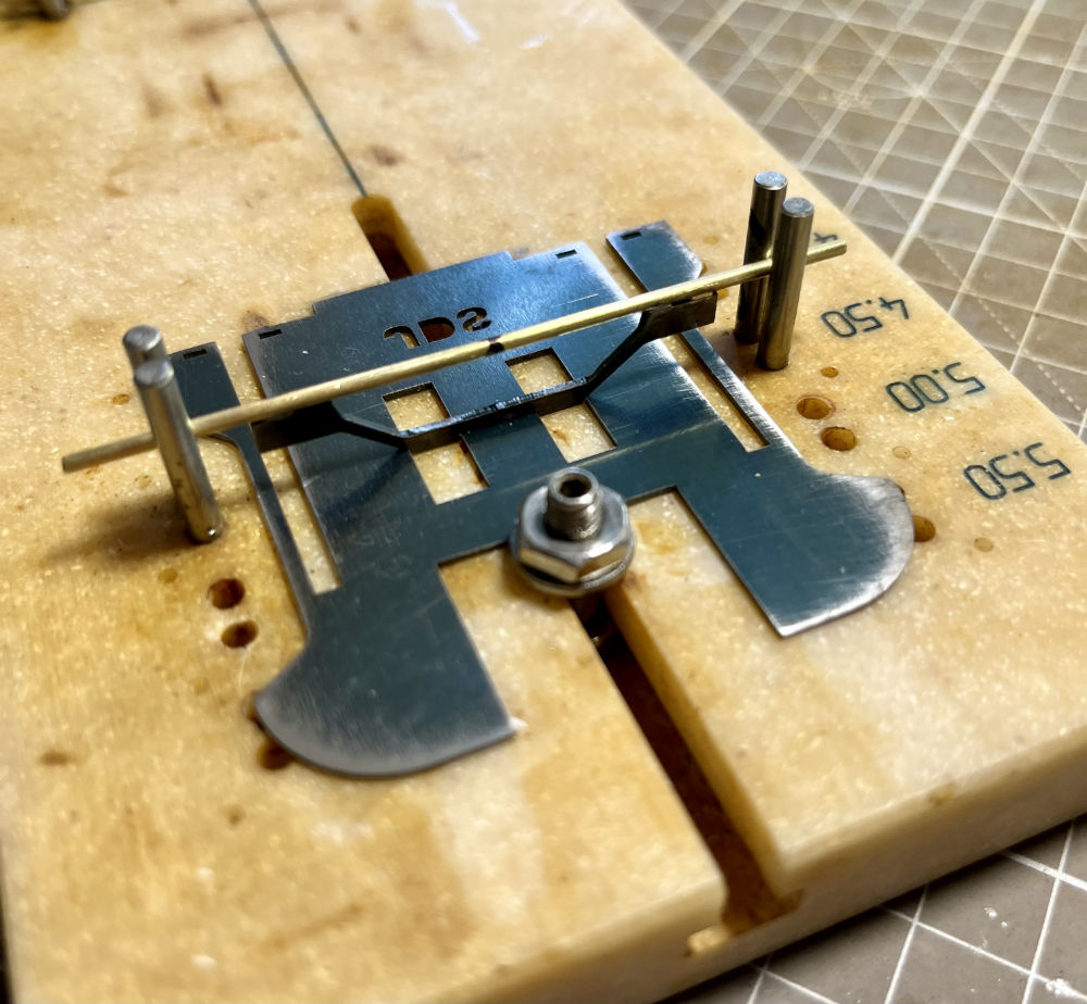
Use your chassis jig’s front axle posts to position the front axle assembly in the nose piece. When positioning your front axle in the nose piece be sure to check the front overhang of your body. Photo 7
NOTE: You want to be sure the front of the chassis behind the front valance and the front of the guide is fully inside the front of the body. On some bodies that have a short front overhang (Vega/Pinto) you may have to notch the lower valance to clear the guide.
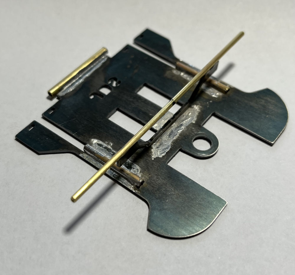
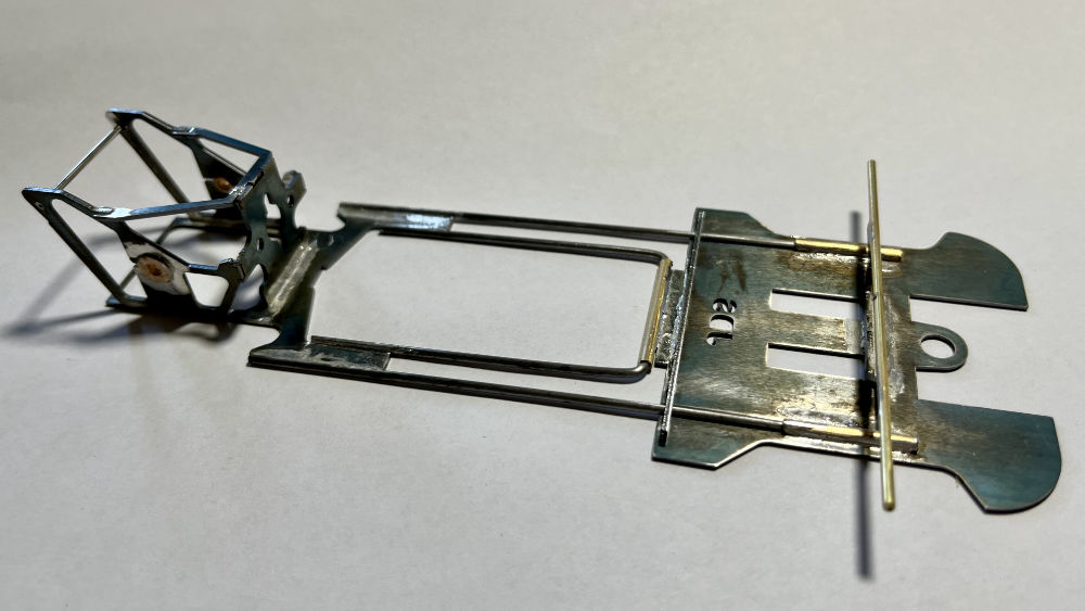
Now cut a 1” length of 1/8” brass tube and solder to the tab at the rear of the nose plate making sure it is centered on the tab. Photo 8
The last step prior to putting the front and back together is soldering in the body mount riser. The riser fits into the four slots at the rear of the nose plate.
Now put the font and rear sections in your chassis jig at the proper wheelbase of your chosen body.
Measure the length from the front of the slot in the nose piece to the rear chassis ears that end at the motor plate and cut two pieces of .062 (or smaller) pieces of music wire to that length.
Slide the music wire into the brass tubes and solder to the rear chassis… DO NOT SOLDER TO THE FRONT OF THE CHASSIS.
Take a piece of .062 music wire and bend it 90 degrees on one end. Don’t worry about the length as you can trim after it’s been bent. Trim the bent end to ¼” to 3/8” in length and slip it into the center brass tube. Lean it down and mark where to cut as it falls on the inner part of the rear chassis ear. Repeat for the other side and solder to the rear chassis section.
The chassis is now complete and ready to mount the body. Photo 9
See our separate instructions on mounting a body.
Thank you for your support!
Be sure to follow JDS Racing Products on Facebook!
Questions or comments may be sent to: info@jdsslotcars.com