
Chassis Instructions – Annililator & Punisher
— photos below —
The JDS “Annihilator” will do just that to the competition. The Annihilator and its brother in arms “The Punisher” (the big tire chassis), feature the strongest motor box in the industry. The unique “wishbone” support, ties the motor plate and axle uprights together, eliminating the flex from the motor’s torque. This unique design provides a consistent gear mesh and virtually eliminates pinion bind.
The Annihilator and Punisher chassis have two separate chassis sections make these chassis the perfect choice for just about any wheelbase Compact to Funny Car. Bracket, class or heads up, these chassis are super consistent and light weight.
Like all JDS chassis, the Annihilator and the Punisher are made from the best .035 spring steel available and are precision cut using the latest laser cutting technology. The main frame rails and wheelie bar supports may be made from JDS stainless tubing or with our new line of music wire with equally good results.
SAFETY PRECAUTIONS
- Always wear safety equipment to protect your face and eyes while assembling the chassis.
- Work in a well-lit location with good ventilation.
- Read and follow all manufacturers’ safety precautions when using tools and soldering equipment.
- Take your time and work carefully. The finished chassis is well worth the time you put into it.
ASSEMBLY INSTRUCTIONS
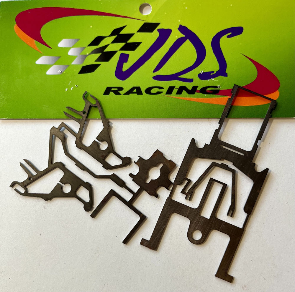
Using 600 grit wet/dry sandpaper, sand the areas on the chassis and uprights parts where you plan to solder. You only need to sand enough to remove the top coating of the bluing on the metal. Photo 1
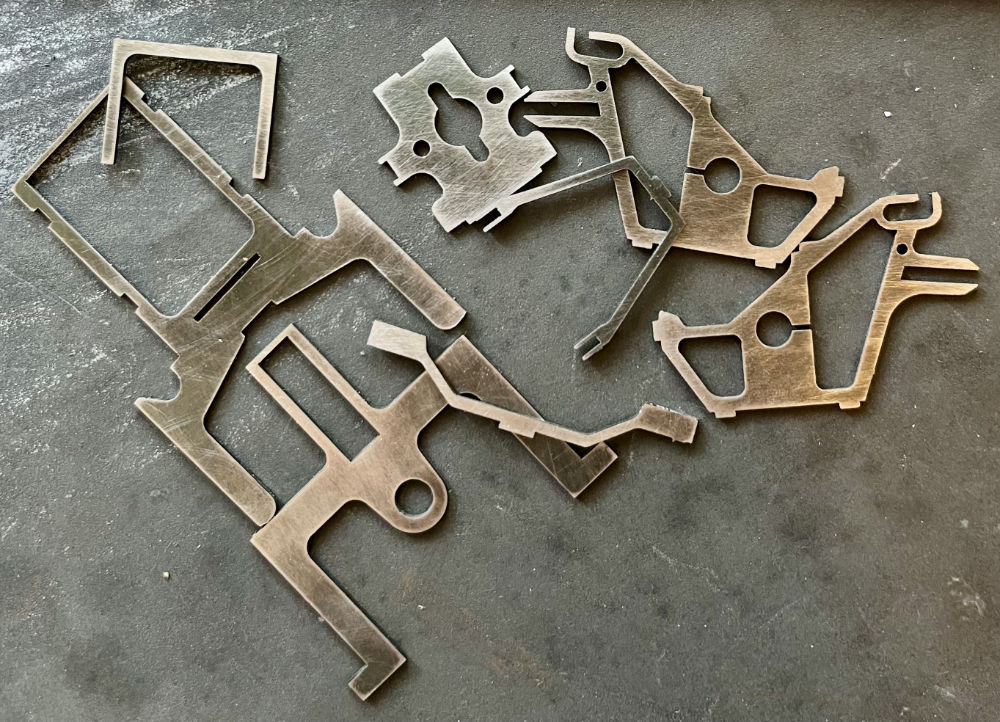
NOTE: You may find it easier to sand the pieces prior to cutting them apart. Simply put a full piece of 600 grit wet dry paper on your bench and rub the chassis on it. Some touch up may be need once cut apart, for this we suggest using a wire wheel in your rotary tool. Photo 2
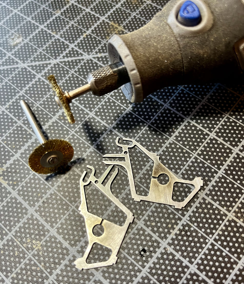
Using your rotary tool and a cutoff wheel carefully cut the pieces apart. Be sure to cut the pieces off flush and remove any burr that may be left behind. Photo 3
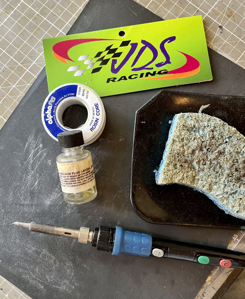
To assemble you will need a good soldering iron (1,000-1,200 degree), some acid flux, solder and a damp sponge to clean the tip of your soldering iron. Photo 4
NOTE: For best results keep your soldering iron tip clean by wiping it on the damp sponge between each solder.
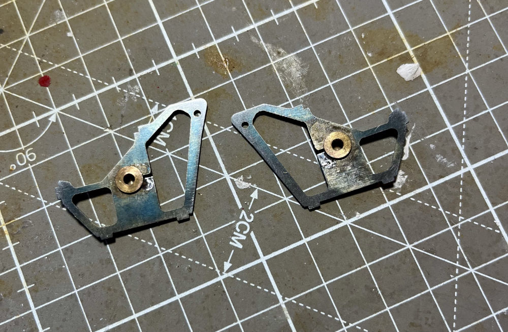
Begin by spot soldering an oilite bushing to each of the axle uprights. Photo 5
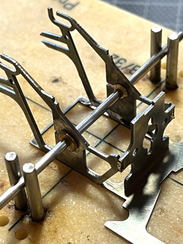
Using your chassis jig place the rear section between the two sets of axle locators on your jig. Then push your axle through the axle uprights and your chassis jig axle locators. Line up the uprights with the slots in the rear chassis section and place the motor plate into the slot in the base then tilt it up and into the tabs on the uprights. Photo 6
NOTE: The hole for the motor bushing is offset. When looking from the front be sure the hole is offset to the right.
Tack solder the uprights to the base at the inside of the rear of the base. Then solder the two upright tabs to the motor plate. Next set the wishbone in place with the two notches over the tabs on the up rights and the tab at the front of the wishbone in the notch in the top of the motor plate. Tack solder the wishbone to the two uprights.
NOTE: Your jig axle should be able to slide freely through the oilites at this point. Photo 7
You may now solder the motor plate to the base and finish soldering the uprights to the base.
Remove the rear section from the jig and flip it over so you may solder the front of the wishbone to the top of the motor plate from the bottom side.
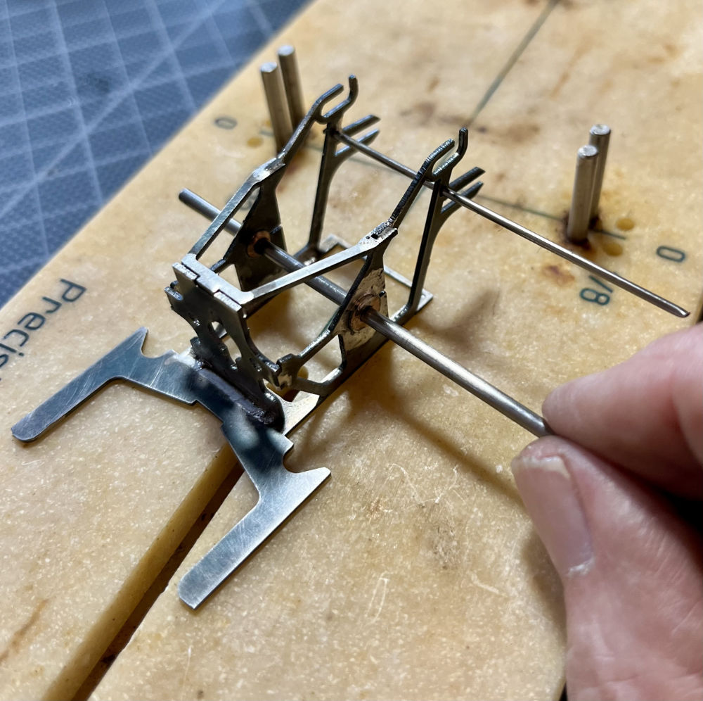
Last take a piece of .050 stainless or music wire and slide it into the two holes at the top rear of the up rights and solder. Use your Dremel to cut this off flush on both sides with the upright.
You may now finish soldering in your oilites.
NOTE: Be sure to put a drop of oil on the axle and slide back and forth to ensure you do not solder the oilites to the axle! If you are using bearings, be sure to put a drop of oil on each side of the bearing to keep the acid flux out of the bearing. Oilites and or bearings also may be installed using two-part epoxy or Loctite.
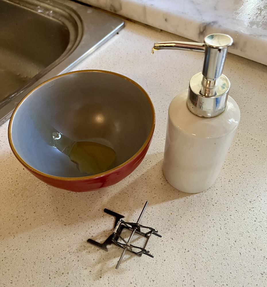
Take the finished rear section of the chassis and wash thoroughly with warm water and dish soap using an old toothbrush to scrub all the solder joints to dissolve the acid flux and keep your chassis rusting. Repeat every time you solder using acid flux. Photos 8 & 9
NOTE: If using a large pinion, when the rear section is complete, you may use your cutoff tool to cut a slot in the motor plate the width of the armature shaft (2mm). This will allow you to easily install your motor with the pinion in place. We do not use a large pinion holed motor plate to accommodate big pinions. Motor plates with large pinion holes can make motor alignment and installation difficult. It is very important that the center of your armature is perfectly aligned and 90 degrees to the rear axle. Our standard sized motor bushing hole makes motor installation a snap and ensures proper alignment.
Now let’s move on to the front section…
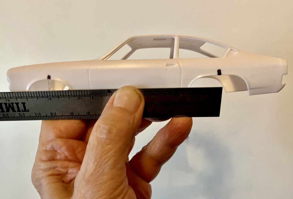
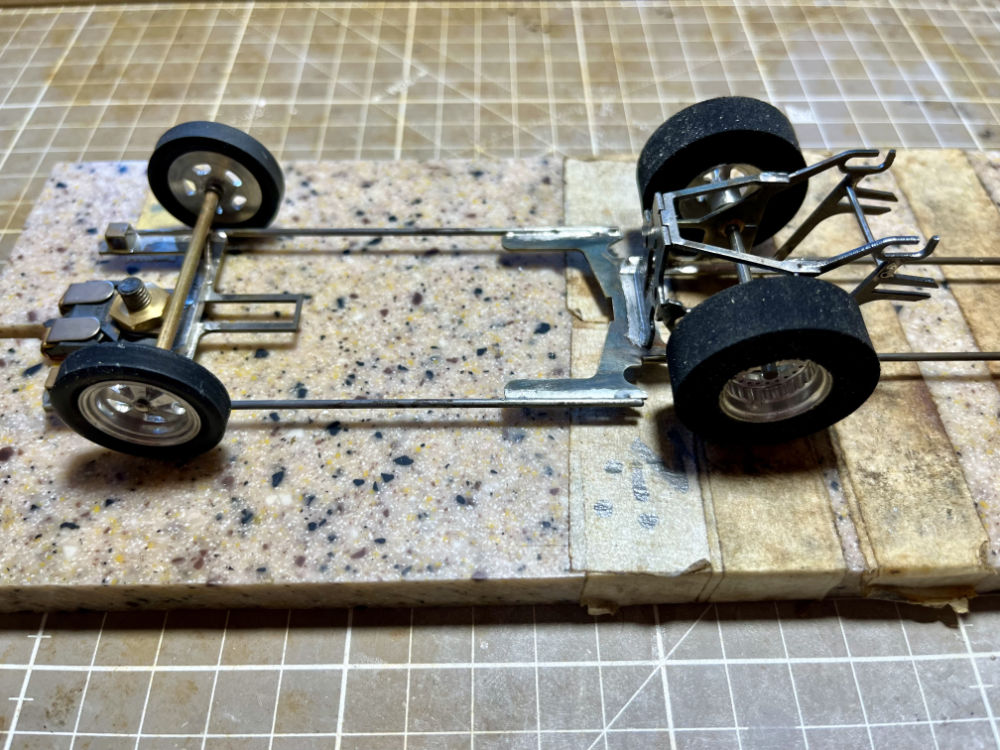
Measure the wheelbase (axle center to axle center) and mark your body’s wheel opening’s center front and rear. Place the rear section in the jig and the front section on the jig’s guidepost. Photo 10
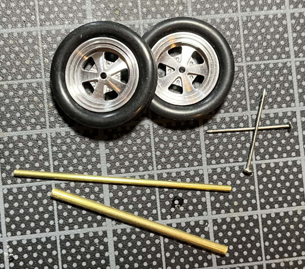
Locate where the front axle support needs to be positioned and solder in place. Be sure you solder the support parallel to the rear axle. The front axle assembly can be made several ways: a single 1/16” brass tube, with soldered on brass retainers to locate the wheels. A single .050 stainless tube or as pictured here a 1/16” brass tube inside a 3/32” brass tube using slightly bent straight pins to secure the wheels. Photo 11
The easiest way is to solder the 1/16” axle or the 1/8” axle carrier to the front axle upright. Then use your jig’s front axle uprights to locate the assembly on the front chassis plate and solder. Photo 12
There is a lot of adjustment available for your front axle position… remember the guide should not stick out from the front of the body. The Vega body used here needed the axle support mounted as far forward as possible and the front chassis “ears” had to be trimmed using a cutoff wheel.
NOTE: Your front axle may be soldered to the front, rear, or on top of the axle support. This provides additional adjustment front to rear – as well as how high your front wheels will be off the track.
NOTE: The front tires should not touch the track. Depending on the style of your front wheels it can be suggested that the front axle is installed after installing the guide, brushes, rear axle and rear wheels. This will set your chassis at ride height and allow you to set your front wheel height as you wish. Use a thick business card under each of the front wheels when soldering the front axle to the support to set them just off the track.
Locate the front and rear sections on your jig or soldering block. Measure the length of
the frame rails that will connect the front and rear sections. Cut two lengths of JDS2014 .082 stainless tubing or .062 music wire to be used as the frame rails.
Solder the two frame rails to the front and rear sections. Then set the body over your frame to double check to be sure the front and rear axles will be in the center of the wheel openings on your body.
Now it’s on to wheelie bars.
NOTE: Wheelie bars can be made in any length with the maximum allowable in most rule sets 5” from the rear axle center to the wheelie bar axle center.
Once you’ve decided on an overall length cut two pieces of .082 stainless tube or .062 music wire and solder to the rear frame and the wheelie bar axle support bracket.
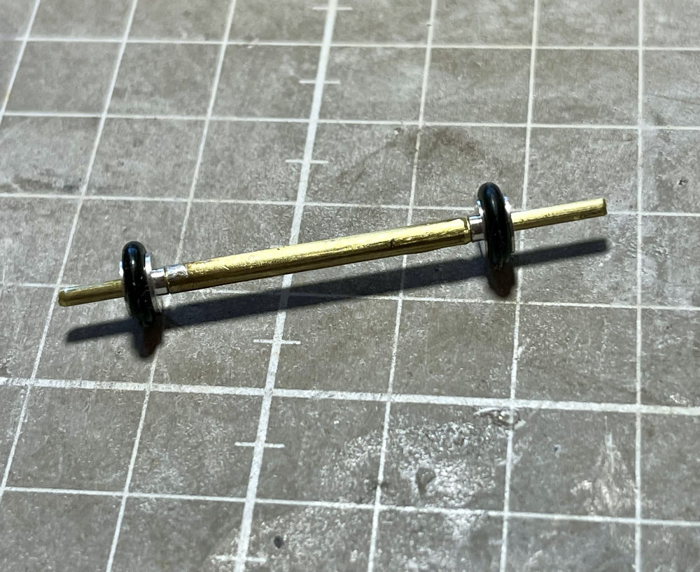
The wheelie bar axle (like the front axle) can be made with a single 1/16” brass tube or a “tube in tube” set up shown here with the 1/16” axle inside a 1/8” brass tube. You will want to install the wheelie bar axle and wheel assembly prior to the wheelie bar support bars. When using the “tube in tube” simply cut a 1” piece of 1/8” brass tube for the carrier and a 1-1/2” piece of 1/16” brass tube for the axle itself. After assembly you will trim the 1/16” axle to the proper length. Leaving the axle long make assembly a bit easier. Photo 13
NOTE: The “tube in tube” axle set up ensures there is no bind when the wheelie bar wheels are on the track… They need to roll free and a drop of oil in the 1/8” tube when assembling is suggested.
NOTE: Track braid heights vary so on your first trip expect to have to adjust your wheelie bars at the track. If you have other cars that have the proper wheelie bar height you can put strips of tape on your tech block under the rear tires until the wheelie bar wheels just touch your tech block. This will ensure your wheelie bars are close to being set prior to going to the track. Adjusting the bar height can be done by adding or removing a washer under your guide or by resoldering your wheelie bar axle tube (when resoldering be sure to wash the area to dilute the acid flux).
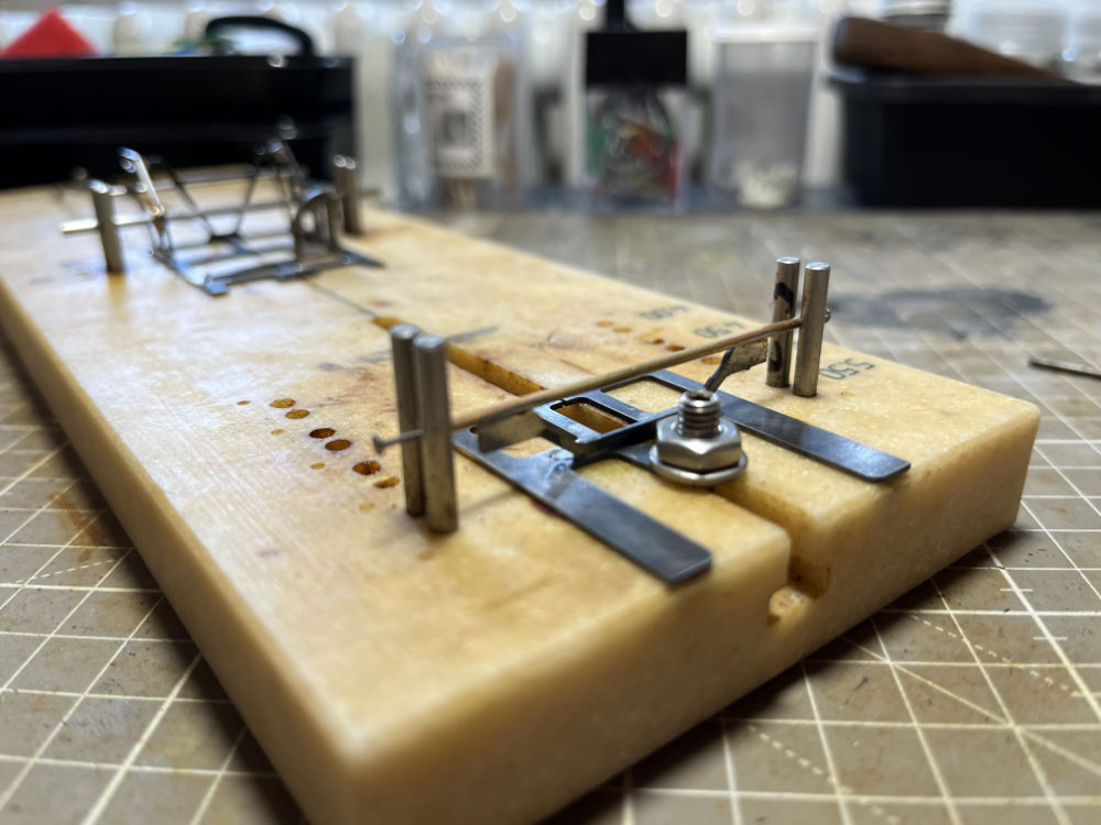
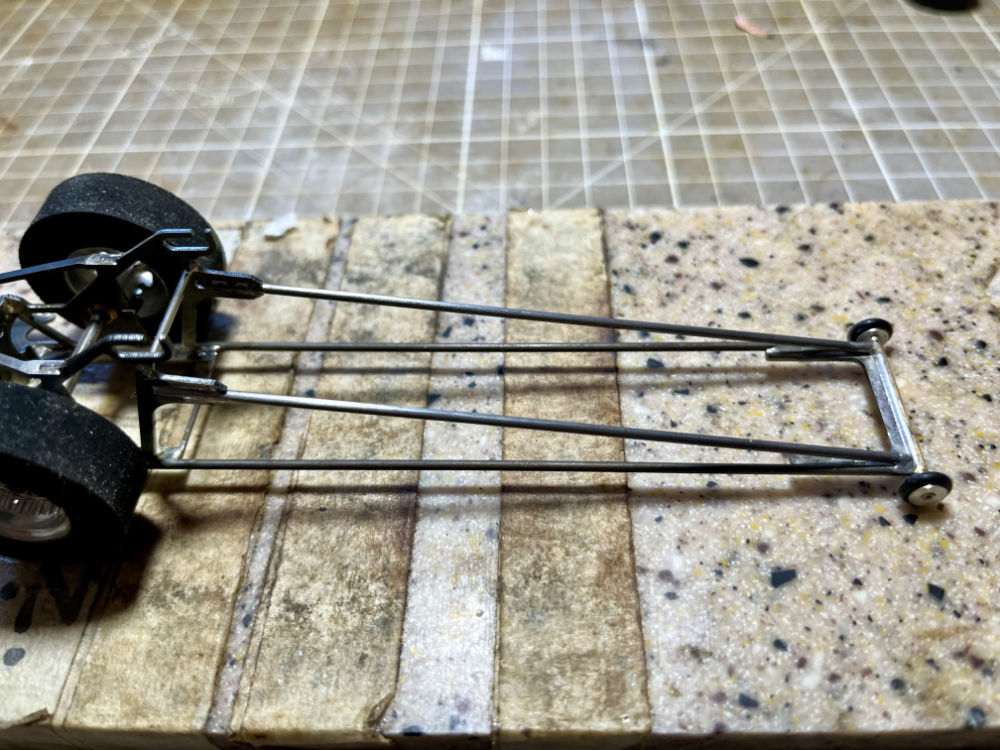
Prior to soldering your wheelie bar axle assembly install you guide, braids, rear axle and rear wheels to get the chassis at the proper ride height. Once assembled check your wheelie bar axle assembly you may have to bend the lower wheelie bar struts down slightly before soldering. Photo 14
Once soldered in place cut your two supports and solder to the axle support then to the uprights. Trim the wheelie bar axle top the proper length and retain the wheels using two straight pins cut to the proper length. The chassis is now complete and ready to mount the body. Photo 15
See our separate instructions on mounting a body.
Thank you for your support! Be sure to follow JDS Racing Products on Facebook!
Questions or comments may be sent to: info@jdsslotcars.com